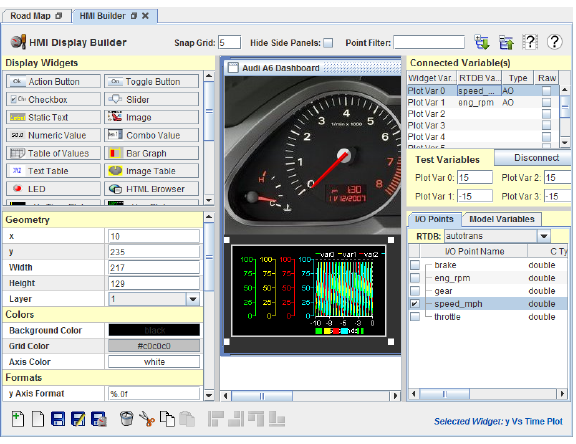
The HMI Display Builder is used to build interactive display windows for use under SIMulation Workbench™.
A display is built by selecting widgets from the widget panel, clicking where you want to place them in the display, configuring their properties such as colors, position and general visual settings, and connecting widget variables to RTDB variables.
Once the display has been created and saved, it can be viewed in the Control Center or in HMI Display. Many of the widgets can be connected to real-time database (RTDB) variables so that the widget will display their values. Most of the widgets can also be used to modify the value of variables.
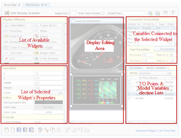
The display builder is divided into several sub-panels :
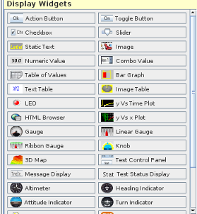
This is the list of widgets available to build a HMI display. A widget internal variable(s) can be connected to RTDB / Model variables. The widget will paint itself to represent the value / states of
its internal variable. For instance, a gauge widget will draw a circular gauge where the needle's position represents the value of the connected variable.
Most of the look and feel of a widget (color, scale, fonts) can be customized to achieve the look wanted.
Scroll through the list to select the widget you want and click on it, then click on the HMI display area to create a widget of this type on the display. When clicking on a specific widget in the HMI build area,
the widget properties will be updated in the widget property panel below and thos properties can be edited.
Clicking on the main display area will enable you to set the general properties of the display itself - Color, background image, size, etc.
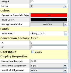
When clicking on a widget in the HMI display area, the properties for the selected widget are displayed. The properties of the widget can be updated by modifying individual properties.
The properties available are specific to each widget. Refer to the help page associated to the widget for a description of each property.
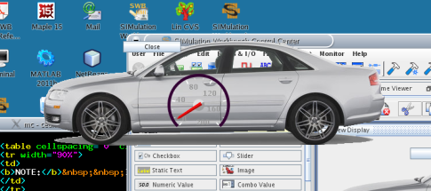
This is where you create your HMI display and layout the various widgets that you want to show on your display.
Select widgets from the widget list and either drag and drop them on the display build area or click on it
to create a widget of the selected type.
This panel shows the list of internal variables in the selected widget. The widget internal variables are specific to a widget. For instance a plot widget will have a long list of variables corresponding to all
the individual traces that can be shown on the plot.
Internal variables that are connected to a RTDB variable will display the variable in the RTDB Variable column.
To disconnect a sepcific variable from its RTDB variable, click in the variable name and hit the disconnect button.
Internal variables can be set to a value to that the user can visualize how the widget will display .
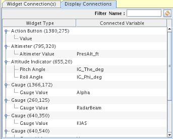
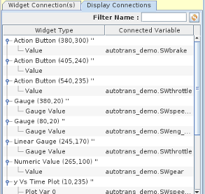 All the widgets present in the specific display as well as their connection to RTDB / Model variables can be shown by clicking on the Display Connections tab.
Clicking on the widget type or connected value in the list will select the widget in the HMI builder area.
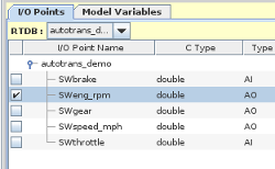
Before you can connect a widget internal variable to an RTDB variable, you must select the RTDB from the list of RTDB's available in the selected project.
After selecting the RTDB, the list of all the variables available in the RTDB will be shown. Connect the selected internal widget variable to the RTDB by clicking on the internal variable
name in the panel above and clicking the check box next to the RTDB variable you want to connect.
You can connect widget internal variables to model parameters as well. Select the model from the drop down list of available to displays its parameters. Click on the check box next to the model parameter to connected
it to the selected widget internal variable.
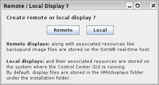
When creating a new HMI display, you must first choose where the display file will reside. The file can be placed either on the client (the system where the Control Center is running) or on the SimWB host (the system that the
control center is logged into. An HMI display loads all its associated resources (background image, HTML file, images for image table widget, etc.) from the same origin it has been loaded from.
In other words, for a display that shows a background image, the image file must be present on the same system - the client or the SimWB host - where the display is loading from.
When loading an existing display , the file selection dialog allows you to browse either the local or remote files.
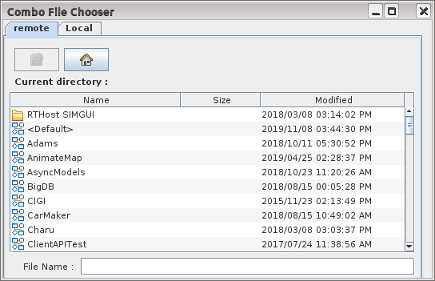
The remote file dialog initially displays all the available locations where a display file can reside on the SimWB host.
The HMI files can reside in individual SimWB projects on the host. In this case, the files and associated image files will be under the project_name/HMI folder where the default project is represented
by the <Default> entry in the list.
The  entry represents the location on the SimWB RT host where the displays corresponding to the Control Center installation are copied.
Entries prefixed with the  icon denote projects on the SimWB RT host. Double click on the project name to navigate to
display or image locations under the project.
icon denote projects on the SimWB RT host. Double click on the project name to navigate to
display or image locations under the project.
Snap GridGrid size in pixels to which widget locations are snapped. The pixel location of the upper left corner of widgets is snapped to the nearest multiple of this value. While the widget is being dragged around, the selection corners will snap to show the final location of the widget. | |||
Hide Side PanelsHides the panels on the left and right edges of the window so that the central display editing area occupies the full width of the window. This makes it easier to position widgets in large displays by avoiding the need to scroll. | |||
Filter PointsRestricts the display of I/O points and model signals and parameters to names containing the regular expression entered in this field. See Regular Expressions. | |||
Expand AllExpands the hierarchy tree for all RTDB variable names in the variable tables. I/O point names with periods in the names are hierarchical names and are displayed as a tree. A.ai000 and A.ai001 are displayed with ai000 and ai001 as children of the A node. Model parameter and signal names with a virgule(/) in the name are treated similarly. |  | ||
Collapse AllCollapses the hierarchy tree for all variable names in the variable tables to show just the top level nodes. |  | ||
DemonstrateOpens a short video clip that demonstrates the basic work flow of this form. |  | ||
HelpOpens this section of the manual. If a widget button or widget is selected, the section documenting that particular widget is opened. |  | ||
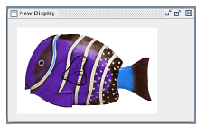
New Display
|  | ||
Open Display...Opens an existing display in the central area. Browse to the .swbd file with the file browser that opens. See HMI File Manager for instructions on how to change the default location for the HMI files. |  | ||
Save DisplaySaves the display in the central area that has focus to the same file as it was opened from or previously saved to. |  | ||
Save Display As...Saves the display in the central area that has focus to a new file name, which is specified with the file browser that opens. See HMI File Manager for instructions on how to change the default location for the HMI files. |  | ||
Save and LaunchSaves the display in the central area that has focus to the same file as it was opened from or previously saved to (if it has been modified) then launches the display. This is very helpful when in an edit & test cycle. |  | ||
DeleteDeletes the selected widget(s) without putting them into the paste buffer. |  | ||
CutDeletes the selected widget(s) and puts them into the paste buffer. |  | ||
CopyCopies the selected widget(s) into the paste buffer. |  | ||
PastePastes the widgets in the paste buffer into the display in the central area that currently has focus. |  | ||
Align LeftAligns the left edge of the selected widgets. |  | ||
Align RightAligns the right edge of the selected widgets. |  | ||
Align TopAligns the top edge of the selected widgets. |  | ||
Align BottomAligns the bottom edge of the selected widgets. |  |
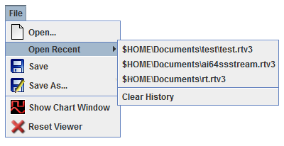
All the lower left corner buttons’ file operations are also available through the File menu. Additionally, there is a dynamically updated Open Recent menu. Every time a display is opened in the editor or launched, it is moved to the head of this list. Selecting a display in this menu opens it in the builder for editing. This list is maintained across program invocations. There is a Clear History menu item in it to erase this history of opened displays.
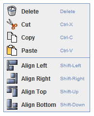
All the lower left corner buttons’ edit operations are also available through the Edit menu.
| NOTE: To select multiple widgets, select the first widget by clicking on it, then holding down the control button while clicking on additional widgets. Multiple widgets may also be selected by clicking on an empty area and dragging with the mouse button still held down to select multiple widgets with a selection lasso. |
The lower right corner indicates the type of widget that has been clicked on most recently. If one of the widget buttons in the upper left panel was clicked on, the indicator will read Click to Insert: Widget Type to indicate that clicking in a display in the central area will insert a widget of that type. If a widget in a display has been selected, it will read Selected Widget: Widget Type to indicate what type of widget a given widget is. Since many widgets are very customizable, it isn’t always clear from appearance which type of widget they are.
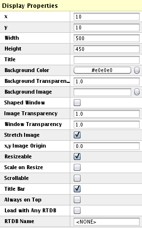
Properties of the HMI Display window. To set the properties of the display window, deselect all items in the display by clicking on an empty area within it.
Horizontal position on the screen where the display will initially open, measured in pixels from the left side of the screen.
Vertical position on the screen where the display will initially open, measured in pixels from the top of the screen.
Initial width in pixels for the display. If the display is not configured to be resizable, this will be the fixed width of the widget.
Initial height in pixels for the display. If the display is not configured to be resizable, this will be the fixed height of the widget.
NOTE: If the specified location and size of the display does not fit within an actual physical screen when the display is opened, it will be moved to the nearest screen that it does fit on.
Title to display in the title bar of the display window. If this is not specified, the title will be set to the name of the display file.
Background color to fill the display with.
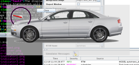
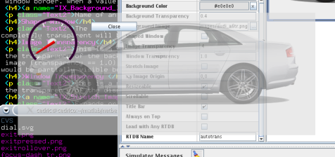
This is a number between 0.0 (completely transparent) and 1.0 (completely opaque) that represents the transparency of the background. A transparency < 1.0 is only supported when the window is undecorated - no window title, no window border. When a value < 1.0 the window decorations are automatically removed.
Name of an image file to fill the display with.
The display window will have the shape cut around the image. All portions of the image that are completely transparent will be removed. The display window decorations are also automatically removed when this option is selected.
This is a number between 0.0 (completely transparent) and 1.0 (completely opaque) that represents the transparency of the background image. You can set a transparency on the display background and have a completely opaque image (transparency == 1.0) or also set a transparency < 1.0 on the background image. In this case, any desktop graphics would be partially visible behind the image as well as behind the rest of the display not covered by the background image.
This is a number between 0.0 (completely transparent) and 1.0 (completely opaque) that represents the transparency of the display window itself. When setting the window transparency, every element contained within the window; i.e. widgets button, background, images assume the same transparency. This is not the case when setting background transparency to < 1.0 where only the background or the background image become transparent but the rest of the elements contained within the window retain their original opacity.
Window Transparency |
|
|
Background Transparency |
|
|
Background and Image Transparency |
|
|
Shaped Window |
|
|
Java and Operating System Considerations |
|
NOTE: All the examples above have no window decorations around the display window.
In order to move a window with no title bar , hold the Alt key down and left click and drag the window.
Expands or shrinks background image so that it fits entirely within the display. If the display is configured to be resizable, the image will expand or shrink with the size of the window.
Comma separated coordinates (x,y) of the background image within the display window. This is only use when the Stretch Image option is off. Negative numbers can be specified.
The background image is stretched to fill the display background:

The background image is not stretched (shown at its native resolution) and its origin is at 20,20:
The background image is not stretched and its origin is at -20,-20:
Permits the display window to be resized by dragging the border. If the display is not resizable, it will always have the fixed width and height assigned to the parameters above.
When checked, all the widgets contained in the display are rescaled proportionally to the window resize.
Enables vertical and horizontal scroll bars in the display window so that when the display is resized to a size smaller than its content, the user can scroll to hidden parts of the display.
Shows the title bar. A window without a title bar cannot be moved by the user.
Keeps display on top of any other windows displayed on the screen.
Permits running the display with any RTDB that has the same variables.
Name of the SIMulation Workbench real-time database that this display expects to be loaded into memory for getting the values of connected variables. This is set by selecting an RTDB from the drop down list of SIMulation Workbench RTDBs on the right side of the display builder screen. An error message will be issued when a display that requires one RTDB is opened while a test is running on the real-time host with a different RTDB unless the Load with Any RTDB option is selected.
If the RTDB name is set to NONE, the display can be run with any RTDB loaded, but cannot access any variables. This is useful for creating a display dedicated to launch tests or other displays.
An HMI display contains a set of widgets that display the values of variables, model signals, and model parameters that exist in the currently loaded real-time database (RTDB). Widgets are associated with specific variables that only exist within a particular RTDB. Only one RTDB can be loaded into memory on the real-time host at a time, so displays (and tests) are associated with a specific RTDB when they are created. This way, the HMI run-time is able to check that the display being opened corresponds to the RTDB loaded in memory and the variables connected to the widgets in that display exist on the real-time host.
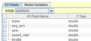
Before a widget can be associated with an RTDB variable, the specific RTDB that the display is being designed for must be selected. This is done via the drop-down combo box of RTDBs as shown in the picture.
The drop-down combo box will show all the RTDBs defined on the real-time host. Once one has been selected, the table below the drop-down combo box is filled with all the variables that exist within the selected RTDB.
In addition to RTDB variables, widgets can also be connected to model parameters and signals. Currently, there is no way to enforce the relationship between displays and specific models, so models are not tied to specific displays. Nevertheless, model parameters and signals are created at run time when a test is started and are accessible as RTDB variables. This only applies to Simulink™ models whose executable has been generated via the tools provided by SimWB as those will extract the model parameters and signals from the generated source code.
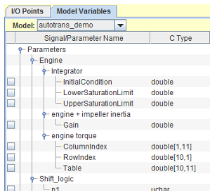
In order to connect a model signal or parameter to a widget, select a model from the model drop-down combo box. The drop-down combo box will show all the models defined on the real-time host. Once one is selected, the table below will be filled with the hierarchy of parameter and signal names defined for the model.
Model parameters are accessible under the Parameters branch in the tree. Model signals are accessible under the Signals branch in the tree. Model signals will only be accessible for Simulink™ models that have been generated with the C-API option on. Only leaves in the tree can be connected to widget variables.
Be aware that as Simulink models are edited, parameters and signals that are used in a display might no longer exist once the model is saved and regenerated. The HMI will show an error message when a display that references variables that don't exist in the RTDB is opened.
Once a model signal or parameter has been connected to widget variable of the selected widget, it will show in the same fashion as I/O points in the list of connected variables.
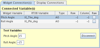
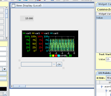
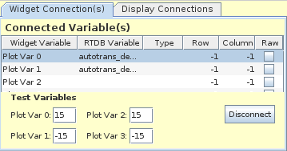
To connect the widget internal variable(s) to RTDB variable(s), first select the widget on the display. The internal widget variable(s) will appear in the Connected Variable(s) list as shown. By default, the first widget variable will be preselected when you selected the widget. Other widget variables may be selected by clicking on them in the table.
To connect an RTDB variable to the selected widget variable, locate the RTDB variable in the tables below the Connected Variable(s) table and click the check box next to its name.
When a widget variable that is already connected to an RTDB variable is selected, the check box next to that RTDB variable will be checked by SimWB. Click in the check box to clear the check mark to disconnect them, or click on the Disconnect button.
when a widget scalar value property is connected to an array type RTDB variable, the row and column index indicates which element of the array should be selected for representation.
You can test how the widget will display for different values of its connected variables by typing values in the entry fields, which are located immediately below the Connected Variable(s) table.
|
The tab shows the list of all the widgets on the selected display along with the RTDB variable names they are connected to.
Toggle the |
|
In addition to numerical variables such as double, float, etc., string variables can also be defined in the RTDB. As with numerical variables, string variables are defined as either input or output. They are really defined as binary buffers with the associated buffer length. A limited set of widgets in the SIMulation Workbench HMI support string variables:
In the HMI, a distinction is made between regular ASCII strings and binary strings. ASCII strings only contain characters defined within the ASCII character set and can thus be displayed and set via data entry as normal text would be.
The content of a binary string is defined by a special format string. The format string consists of a comma-separated list of entries that specify the subfields of the binary string. Each entry contains the type and value specifiers of the subfield. For some widgets, the value may be specified as the value of a data entry field, otherwise the value is an integer constant.
The valid type specifiers are:
The number following the I1 specifier is to be packed as a single byte. This specifier is optional for specifying the value of a single byte with an integer value.
The number following the I2 specifier is to be packed in the buffer as a little-endian 2-byte short number.
The number following the I4 specifier is to be packed in the buffer as a little-endian 4-byte int number.
The value specifier is a simple integer value or a field specifier, which specifies which field in a data entry form to get the value from with an F followed by the number of field in the data entry form (numbered from 0).
3,I14,I2F0,I4F1
The binary string will be:
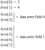
In the case of the Combo Value widget (see Combo Value), the data entry fields are part of the combo value widget itself.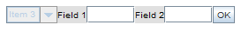
In the case of the Numeric Value widget (see Numeric Value), the data entry fields are in the data entry dialog that appears when the value is edited, the associated variable is defined as a binary string, and the binary string format contains Fx field specifiers.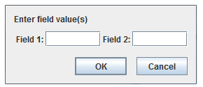
Action Buttons, Toggle Buttons and Checkboxes do not support subfield data entry, and in this case, the Fx field specifier is not used.
For those widgets, we would specify the value to send on click, for example:
0,I412,I222
Where byte zero is a 0, bytes one to four are the little-endian 32-bit integer value 12 and bytes five and six are packed with little-endian 16-bit integer value 22.
The HMI run-time includes the ability of calling some SIMulation Workbench™ or user-defined routines.
The function calls are executed by the guirpcsrv process. There is one instance of this process for each instance of the HMI run-time. The call requests are sent via a SIMulation Workbench™ specific protocol over the network connection that is created between the HMI run-time and the corresponding instance of the guirpcsrv process.
Not all SIMulation Workbench functions supported by the API are callable via this mechanism.
Only the functions that accept scalar arguments (no pointers) or string constant (no quote) and return an integer error code are defined as callable by the HMI run-time.
The list of SIMulation Workbench functions callable by the HMI run-time is defined in the simwbfunctionlist.txt file in the /usr/local/ccursim/GUIHooks directory. This is an ASCII file generated automatically with each SIMulation Workbench release and is included in the standard release. This is the content of the file distributed with a typical SIMulation Workbench:
function=ccurAsyncIO_afdxTXQueueNowName(char *)
function=ccurAsyncIO_afdxTXQueueNowMsg(int ,int ,char * )
function=ccurAsyncIO_afdxSetTxRateMsg(int ,int ,char *,int )
function=ccurAsyncIO_afdxSetTxRate(char * ,int )
function=ccurAsyncIO_afdxGetTxRate(char * )
function=ccurAsyncIO_afdxGetDefaultTxRate(char * )
function=ccurAsyncIO_afdxGetTxFlags(char * )
function=ccurAsyncIO_afdxGetDefaultTxFlags(char * )
function=ccurAsyncIO_afdxGetTxRateMsg(int ,int ,char *)
function=ccurAsyncIO_afdxGetDefaultTxRateMsg(int ,int ,char *)
function=ccurAsyncIO_afdxGetTxFlagsMsg(int ,int ,char *)
function=ccurAsyncIO_afdxGetDefaultTxFlagsMsg(int ,int ,char *)
function=ccurAsyncIO_afdxSetTxScheduledToFIFO(char * )
function=ccurAsyncIO_afdxSetTxScheduledToFIFOMsg(int ,int ,char *)
function=ccurAsyncIO_afdxSetTxFIFOToScheduled(char *,int )
function=ccurAsyncIO_afdxSetTxFIFOToScheduledMsg(int ,int ,char *,int )
function=ccurAsyncIO_afdxSetFIFOTxOnChange(char *,int )
function=ccurAsyncIO_afdxSetFIFOTxOnChangeMsg(int ,int ,char *,int )
function=ccurAsyncIO_afdxPauseMsg(int ,int ,char * )
function=ccurAsyncIO_afdxPauseItemMsgName(char * )
function=ccurAsyncIO_afdxResumeMsg(int ,int ,char * )
function=ccurAsyncIO_afdxResumeItemMsgName(char * )
function=ccurAsyncIO_afdxSetNetConfigName(char * ,int ,int )
function=ccurAsyncIO_afdxSetNetConfigMsg(int ,int ,char * ,int ,int )
function=ccurAsyncIO_ao16SetFrequencyWave(int ,int ,double ,char * )
function=ccurAsyncIO_ao16SetAmplitudeBias(int ,int ,double , double )
function=ccurAsyncIO_ao16SetPhase(int ,int ,double )
function=ccurAsyncIO_ao16Resume(int )
function=ccurAsyncIO_ao16Pause(int )
function=ccurAsyncIO_ao16Start(int )
function=ccurAsyncIO_ao16Stop(int )
function=ccurAsyncIO_ao16SetFilter(int ,int )
function=ccurAsyncIO_arinc429TXQueueNowName(char *)
function=ccurAsyncIO_arinc429TXQueueNowLabel(int ,int ,int ,int )
function=ccurAsyncIO_arinc429SetInvertParity(char *,int )
function=ccurAsyncIO_arinc429SetTxRateLabel(int ,int ,int ,int ,int ,int )
function=ccurAsyncIO_arinc429SetTxRate(char * ,int )
function=ccurAsyncIO_arinc429SetTxRate(char * ,int )
function=ccurAsyncIO_arinc429GetTxRate(char * )
function=ccurAsyncIO_arinc429GetDefaultTxRate(char * )
function=ccurAsyncIO_arinc429GetTxFlags(char * )
function=ccurAsyncIO_arinc429GetDefaultTxFlags(char * )
function=ccurAsyncIO_arinc429GetTxRateLabel(int ,int ,int ,int )
function=ccurAsyncIO_arinc429GetDefaultTxRateLabel(int ,int ,int ,int )
function=ccurAsyncIO_arinc429GetTxFlagsLabel(int ,int ,int ,int )
function=ccurAsyncIO_arinc429GetDefaultTxFlagsLabel(int ,int ,int ,int )
function=ccurAsyncIO_arinc429SetTxScheduledToFIFO(char * )
function=ccurAsyncIO_arinc429SetTxFIFOToScheduled(char *,int )
function=ccurAsyncIO_arinc429SetFIFOTxOnChange(char *,int )
function=ccurAsyncIO_arinc429HaltPointChannel(char * )
function=ccurAsyncIO_arinc429StartPointChannel(char * )
function=ccurAsyncIO_arinc429HaltChannel(int ,int ,int )
function=ccurAsyncIO_arinc429StartChannel(int ,int ,int )
function=ccurAsyncIO_arinc429PauseLabel(int ,int ,int ,int )
function=ccurAsyncIO_arinc429PauseItemLabelName(char * )
function=ccurAsyncIO_arinc429ResumeLabel(int ,int ,int ,int )
function=ccurAsyncIO_arinc429ResumeItemLabelName(char * )
function=ccurAsyncIO_canTXQueueNowName(char * )
function=ccurAsyncIO_canTXQueueNowCANId(int ,int ,int )
function=ccurAsyncIO_canSetFIFOTxOnChange(char *,int )
function=ccurAsyncIO_canSetFIFOTxOnChangeCANId(int ,int ,int ,int )
function=ccurAsyncIO_canResumeCANId(int ,int ,int )
function=ccurAsyncIO_canPauseCANId(int ,int ,int )
function=ccurAsyncIO_canSetTxRateCANId(int ,int ,int ,int )
function=ccurAsyncIO_canGetTxRateCANId(int ,int ,int )
function=ccurAsyncIO_canGetDefaultTxRateCANId(int ,int ,int )
function=ccurAsyncIO_canGetTxFlagsCANId(int ,int ,int )
function=ccurAsyncIO_canGetDefaultTxFlagsCANId(int ,int ,int )
function=ccurAsyncIO_canSetTxScheduledToFIFOCANId(int ,int ,int )
function=ccurAsyncIO_canSetTxFIFOToScheduledCANId(int ,int ,int ,int )
function=ccurAsyncIO_canGetTxFlags(char * )
function=ccurAsyncIO_canGetDefaultTxFlags(char * )
function=ccurAsyncIO_canSetTxRate(char * ,int )
function=ccurAsyncIO_canSetTxFIFOToScheduled(char *,int )
function=ccurAsyncIO_canGetTxRate(char * )
function=ccurAsyncIO_canGetDefaultTxRate(char * )
function=ccurAsyncIO_canSetTxScheduledToFIFO(char * )
function=ccurAsyncIO_netIOTXQueueNowName(char *)
function=ccurAsyncIO_netIOTXQueueNowMsg(int ,char * )
function=ccurAsyncIO_netIOSetTxRateMsg(int ,char *,int )
function=ccurAsyncIO_netIOSetTxRate(char * ,int )
function=ccurAsyncIO_netIOGetTxRate(char * )
function=ccurAsyncIO_netIOGetDefaultTxRate(char * )
function=ccurAsyncIO_netIOGetTxFlags(char * )
function=ccurAsyncIO_netIOGetDefaultTxFlags(char * )
function=ccurAsyncIO_netIOGetTxRateMsg(int ,char *)
function=ccurAsyncIO_netIOGetDefaultTxRateMsg(int ,char *)
function=ccurAsyncIO_netIOGetTxFlagsMsg(int ,char *)
function=ccurAsyncIO_netIOGetDefaultTxFlagsMsg(int ,char *)
function=ccurAsyncIO_netIOSetTxScheduledToFIFO(char * )
function=ccurAsyncIO_netIOSetTxScheduledToFIFOMsg(int ,char * )
function=ccurAsyncIO_netIOSetTxFIFOToScheduled(char *,int )
function=ccurAsyncIO_netIOSetTxFIFOToScheduledMsg(int ,char *,int )
function=ccurAsyncIO_netIOSetFIFOTxOnChange(char *,int )
function=ccurAsyncIO_netIOSetFIFOTxOnChangeMsg(int ,char *,int )
function=ccurAsyncIO_netIOPauseMsg(int ,char * )
function=ccurAsyncIO_netIOPauseItemMsgName(char * )
function=ccurAsyncIO_netIOResumeMsg(int ,char * )
function=ccurAsyncIO_netIOResumeItemMsgName(char * )
function=ccurEB5100_startCommunication(int )
function=ccurEB5100_stopCommunication(int )
function=ccurEB5100_commitFrame(int ,int )
function=ccurEB5100_enableSendFrame(int ,int )
function=ccurEB5100_disableSendFrame(int ,int ,int ,int )
function=ccurEB5100_getLastError(int )
function=ccurGen_addGenerator(char *,int , int ,float ,float ,float ,float , float ,float ,double , char * )
function=ccurGen_addAsamGenerator(char *, char *)
function=ccurGen_startAllGenerators()
function=ccurGen_stopAllGenerators()
function=ccurGen_removeAllGenerators()
function=ccurGen_rampToValue(char *,double ,double , int ,double )
function=ccurGen_rampRate(char *,double ,double ,int ,double )
function=ccurRTDB_getCVTValueDouble(char *)
function=ccurRTDB_getAlternateValueDouble(char *)
function=ccurRTDB_getCurrentValueDouble(char *)
function=ccurRTDB_setCVTValueDouble(char *,double )
function=ccurRTDB_setAlternateValueDouble(char *,double )
function=ccurRTDB_setCurrentValueDouble(char *,double )
function=ccurRTDB_setLoggingEnable(char *,char )
function=ccurRTDB_takeSpareItem(char *,int ,int )
function=ccurRTDB_setAlternateFlag(char *,int )
function=ccurRTDB_setOperatorFlag(char *,int )
function=ccurRTDB_resetToDefault()
function=ccurRTDB_resumeDLogger()
function=ccurRTDB_pauseDLogger()
function=ccurRTDB_stopCircularLogger()
function=ccurRTDB_writeStdOut(char *)
function=ccurSched_pause()
function=ccurSched_resume()
function=ccurSched_nonRT()
function=ccurSched_resumeRT()
function=ccurSched_step(int )
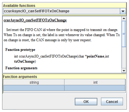
The function prototype as well as the API is shown when you select a function.
The parameters to the function can be passed as constant; i.e. 3.5 or as $value to represent the value of the RTDB variable or the value connected to the widget. For instance in the case
of a slider widget, the $value would be the value set by the widget when moving the slider thumb.
The token $variablename can also be used to represent the name of the RTDB item the widget is connected to and will be substituted in the call before calling the remote function.
The user can defined a library with their own remotely callable functions. The user functions are listed in
$SIMWB_ROOT/GUIHooks/guifunctionlist.txt
The user must build a dynamic library (.so) so that it can be linked in at run-time into the guirpcsrv process.
See the example provided in the $SIMWB_ROOT/GUIHooks/ directory.
| HMI File Manager |

|
 button to enable/disable incremental search while the filter field is edited. When incremental search is on,
refreshing might be significantly slower as the list needs to be recreated whenever a new character is typed in the filter field.
button to enable/disable incremental search while the filter field is edited. When incremental search is on,
refreshing might be significantly slower as the list needs to be recreated whenever a new character is typed in the filter field.